Heater Control Valve Troubleshooting
- Model & Year: 91-97 8-Series
- Expertise: Beginner
- Date: December 2011
- Updated:
- Time Estimate: varies
Tools Required
- Digital voltmeter
- Basic hand tools
Facilities Needed
- Work Bench
Parts Required
- New, used, or rebuilt heater valve
Getting Started
Are you getting nothing but hot air from your vents? Your heater control valves (HCV's) are probably misbehaving, now a common failure. The HCV's are located at the left rear of the engine bay (driver side). The problem could be either mechanical (ex: defective internal seals) or electrical (ex: defective circuit boards).
Troubleshooting this problem is straightforward, requiring only basic electric diagnostic skills and a multimeter. Once the fault is isolated, you can proceed with parts repair or replacement.
My car had a faulty driver side (left) HCV which took almost a year to resolve (see this thread in BimmerForums). The following procedure and notes are based on this experience. It is written for the amateur do-it-yourselfer and therefore avoids circuit board analysis, and instead focuses on component replacement or repair. Furthermore, it assumes no wiring faults are present. Therefore, before replacing a component, you may want to test its respective wiring for continuity in order to be absolutely sure.
TIP: Before beginning, I would suggest an IHKA (HVAC) fault code readout from your favorite indy mechanic or dealership. It's usually free. Why not utilize the diagnostic capability built into your 8-series?
My car showed "left side heater valve". Info like this will help focus your troubleshooting.
Begin by testing electric signals on the HCV connector, and then move on to test the HCV unit itself. Below is the pertinent section of the official wiring diagram:
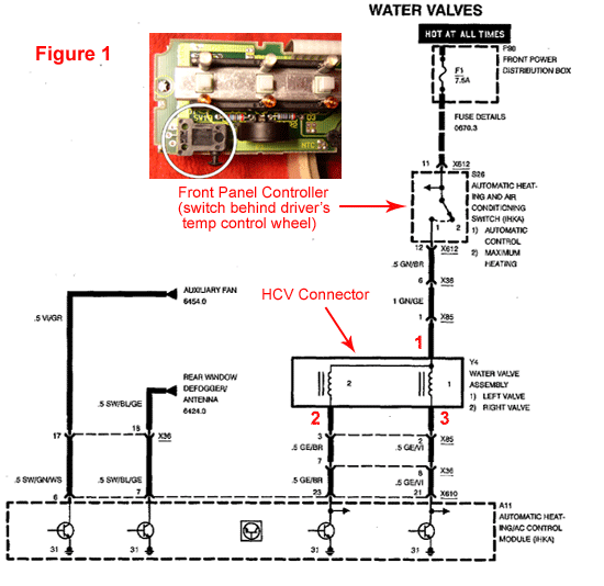
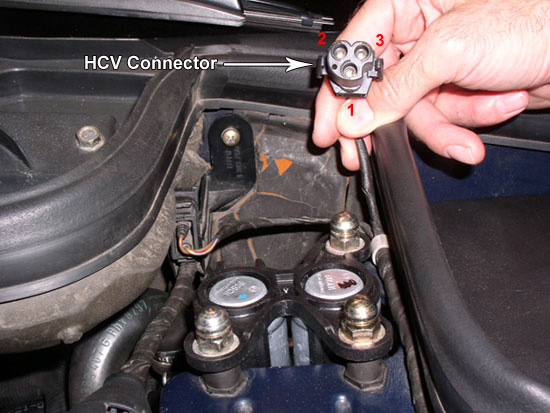
The HCV connector with corresponding red numbered terminals is shown below:
Procedure
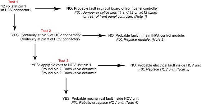
Refer to the following flowchart for an overview, with test details and supporting notes below:
Heater Control Valve Troubleshooting - print quality diagram (PDF format).
TEST 1 - Set your multimeter to test volts (DC). With both ignition and HVAC system "on", place one probe into connector pin1. Ground the other probe to the chassis (strut tower mounting bolts are convenient). The reading should be close to 12 volts (ex: 11.89). See note 1 below to address fault.
TEST 2 - Set your multimeter to test resistance (ohms). With both ignition and HVAC system "on", place one probe into connector pin 2. Ground the other probe to the chassis (strut tower mounting bolts are convenient). The reading should be some varying non-infinite number. The actual value is not important - as long as it's not infinite. Repeat test for pin 3. See note 2 below to address fault(s).
TEST 3 - This test is performed on the HCV unit itself, NOT the connector. You will need a 12 volt power source. I used the jumper points under the hood and jumper cables. I secured nails in the cable's jaws to serve as probes. Be careful not to touch the probes together! With 12 volts applied to HCV terminal 1, ground terminal 2. You should hear a "thunk" as the valve actuates. Repeat test for terminal 3. No "thunk"? See note 3 below. Otherwise, see note 4 below.
NOTE 1 - Barring a wiring fault, this outcome is probably due to a faulty switch behind the driver side temperature control wheel on the front panel controller circuit board. This switch controls power to the heater valves, and is either on or off. When off, no power flows and the heater valves are full open. By jumpering or splicing pins 11 and 12, the switch is effectively bypassed allowing power to flow. Once bypassed, you will no longer be able to fully open the heater valves for full heat. However, any difference in heat output will be minimal. An example:
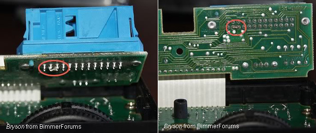
Removing the front panel controller requires console trim removal and disassembly of the controller. An alternative which does not require controller disassembly is splicing wire 11 and 12 together.
NOTE 2 - Barring a wiring fault, this outcome is probably due to faulty transistors on the main A11 (IHKA) control module, located under the dash, in front of the air distribution box. The transistors control both left and right heater valves. At this time, replacement is the only known fix. The module is complex:
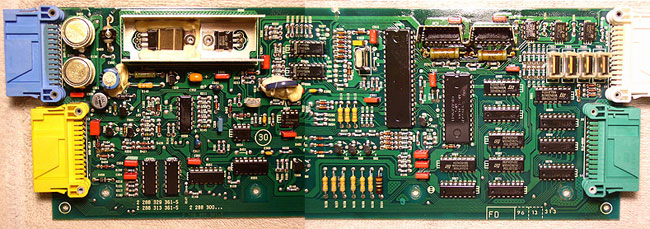
Lower trim removal on both driver and passenger side is required to access this "black box". It is secured by a plastic tab to the air box. Press tab in (rearward) and pull out from passenger side after disconnecting the four wiring harnesses (white/green - left, blue/yellow - right). A new module is cost prohibitive, if available at all. Source used parts from BimmerForums or eBay. Currently, prices range from $300-$400.
NOTE 3 - Probable internal electric fault or broken valve. Replace HCV unit. Prices start around $180. HCV removal is facilitated by first removing the fresh air cowl at the rear of the engine bay. There is a small 7mm screw on each side which holds the cowl. Be sure to use a magnetic socket, or you will drop the screw in the bowels of the engine bay. Also, be careful when separating the water hoses from the HCV's attached auxiliary water pump as the plastic neck may crack.
NOTE 4 - Probable faulty internal seals. Either rebuild or replace the HCV unit. Seal rebuild kits are available from Wokke on BimmerForums. See note 3 for tips on removal.