Lumbar Valve Replacement
- Model & Year: 95-01 7-Series, U.S.
- Expertise: Beginner
- Date: April 2015
- Updated: April 27, 2024
- Time Estimate: 3 hours
Tools Required
- T25 torx driver
- Misc hand tools
- Bentley or Haynes manual (optional)
Facilities Needed
- None
Parts Required
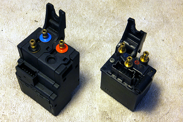
- (1) Lumbar Valve Unit: p/n 67-66-8-385-632, list: $129, used: about $25 (samples shown above)
Getting Started
Does your front seat lumbar support deflate after a few minutes or otherwise fail to hold pressure? You probably have a failed valve unit inside the seat. This is an easy repair that can be accomplished in an afternoon.
These valve units are part of the "lordosis pad" system and function to pump air into one or both air chambers (upper and lower) behind the seatback cushion. Typically, the internal check-valve fails, allowing air to escape. The unit may even develop cracks in its plastic body, releasing air.
I discovered the valve units come in at least two different sizes and are interchangeable (see image above). New valve units are expensive, so most people turn to used parts instead. However, only with a new part can you be assured of correct check-valve operation. The seatback panel will need to be removed for access.
Procedure
1) Position front upper seatback forward, then recline the whole seatback forward.
2) Remove seatback panels.
This is the most difficult part of the procedure. In my experience, there's no method that works every time. Generally speaking, remove the upper seatback panel first by pulling downward while pulling the bottom outward. The upper panel may not need to be removed if the upper section is reclined fully forward.
Next, grab the bottom of the lower seatback panel (somewhere) and pull out while shifting the whole thing back and forth (left and right). It may take several attempts of pulling and shifting but it should eventually release its bottom clips. Then lift the panel off its upper hangers.
3) Locate the valve unit in lower left of seatback. See image:
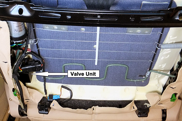
The valve unit will be partially hidden by various other wires and connectors; unplug and move them out of the way.
The air line which is clear or transparent is the main air supply coming from the air pump under the seat, while the blue line controls the upper lumbar chamber and the red line controls the lower chamber. (See image below.)
4) Unplug valve unit electrical connector. Prying carefully with a small screwdriver for leverage may help in this confined space. Needle nose pliers may also help remove the plug.
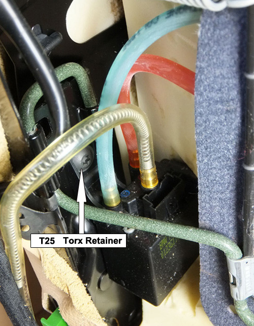
5) Remove the T25 retainer screw and pull valve unit up and off its retaining slot in the seatback frame. See image above. Position the valve unit so that the air lines may be easily reached.
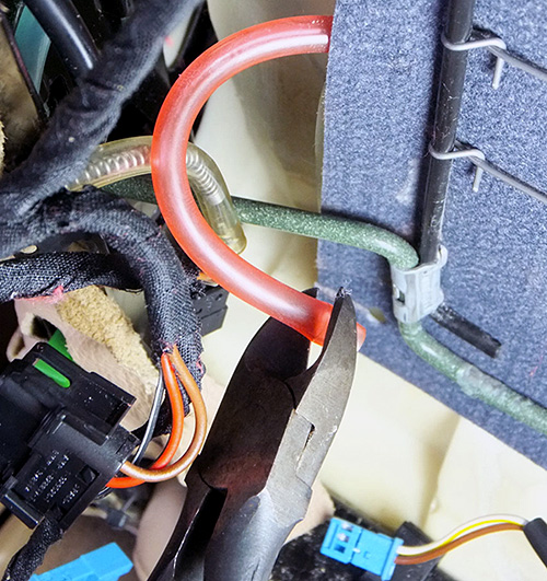
6) Remove all three air lines (clear, blue and red) by pulling straight off. Use a small screwdriver or pry tool for leverage to help loosen the bond between nipple and line. If lines refuse to budge, they can be cut at the nipple.
7) In order to ensure an air-tight seal with the replacement valve unit, snip the deformed, bloated ends of all three air lines where they connected to the old valve unit (if not already done in step 6), as illustrated below:
8) Install the replacement valve unit in reverse order.
Before re-installing seatback panels, test operation of the replacement valve unit:
- Fully inflate lumber chambers by pressing lumbar switch forward. Listen and watch for inflation.
- With chambers inflated, listen for air leakage around bottom of replacement valve unit. There should be none.
- Press lumbar switch up and down; listen for valve unit operation as it moves air between chambers.
- Press lumbar switch for deflate (rearward). Listen for air release at bottom of valve unit.
Now, enjoy a fully functional "lordosis" system!