Electronic Throttle Faults & Repair
- Model & Year: 99-00 5-Series
- Expertise: Intermediate
- Date: October 14, 2019
- Updated: June 27, 2024
- Time Estimate: 8-12 hours
Tools Required
- Soldering Iron
- Basic hand tools
- Bentley or Haynes manual (optional)
Facilities Needed
- Garage or level surface
Parts Required
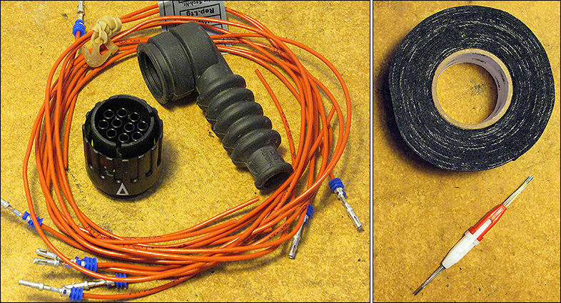
- Plug Connector (10-pin), 12-52-1-744-870, $9 list,
- (10) Pin Wires, 61-13-0-007-656, $6 list (each),
- Rubber Grommet, 12-52-1-703-522, $6 list
- Heat Wrap, various, about $7
- Heat-Shrink Tubing (not shown), various, about $8
- Pin Insertion Tool, various, about $5
NOTE: Online part catalogs such as RealOEM.com specify only 8 pin wires for the connector. This is wrong. 10 pin wires should be purchased for all 10 pin locations.
Getting Started
Has your '99-'00 6-cylinder BMW experienced intermittent problems with its electronic throttle? Do you have dash warning lights such as Check Engine, EML, and ASC traction control (as in image below)? Have you previously replaced a defective throttle only to suffer what appears to be a repeat of this matter?

It's entirely possible that your throttle body (also known by its German acronym, MDK) is simply experiencing an electrical problem with its 10-pin connector.
Common faults displayed in scan tools include "Pedal sensor (PWG) potentiometer #1" and "Motorized throttle (MDK) final stage failure". Your car will run poorly as the engine computer reverts to "limp home" mode with only minimal throttle response.
Diagnosis
To confirm the problem, locate the throttle's partially obscured 10-pin connector (underneath the intake manifold) and shake the wire bundle leading into the connector. Then, clear the faults with a scan tool. If the faults do not immediatley re-appear, there's most likely a faulty contact in the connector.
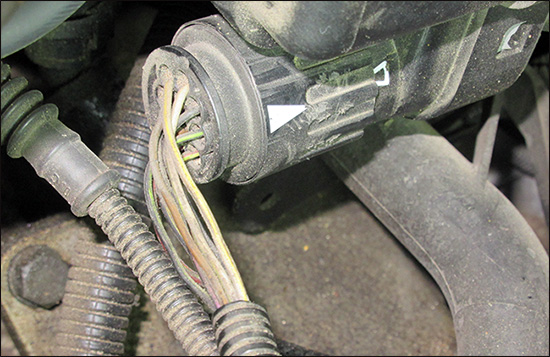
I highly suspect this problem stems from the unprotected nature of the connector's wire bundle, as shown in image below. Facing the direction of travel, contaminants such as dirt and water can easily accummulate inside the plug causing corrosion and other faults. Replacing this connector plug and its pin wires should correct the problem.
NOTE: This procedure is applicable to all '99-'00 BMW's with M52TU 6-cylinder engines. These engines featured a hybrid throttle controlled by both cable and electronics. Previous engines were completely cable operated, while later engines were fully electronic (drive-by-wire). M62TU V8 engines also suffer from this issue.
The new connector accepts 10 special pin wires, with blue rubber seal rings behind the pin recepticle, to keep out water and debris. A protective grommet will then cover the entire wire bundle and hopefully provide permanent resolution of this issue.
Considerations
The following procedure is time consuming, requiring patience and attention-to-detail. For space in which to work, the airbox and all associated ducts upstream of the throttle body need to be removed, along with the driver-side cabin filter housing and duct. If working at a leisurely pace, allow one day to take everything apart and a second day to put it back together.
Since this repair involves sensitive electric circuits, it's important when splicing wires to ensure a good connection by the use of solder. A soldered connection also provides a physically secure union.
Inserting the pin wires into the new connector will require more force than simply pushing on the wire. A "pin tool" will be needed to apply force to the back of the pin as it's inserted, such as the type used when pinning DB25 connections. See Parts Required above. These tools can be purchased on Amazon or eBay for about $5. And high-temperature friction tape should be used to wrap any remaining exposed wires.
This is also an opportunity to address other issues discovered during the procedure. For example, the throttle cable's plastic sheath may be deteriorating from age, exposing the metal sheath underneath. Peel away the failing sheath and protect the cable with the heat wrap.
Procedure
Prep Work
1) Remove driver-side cabin air filter box and air duct.
2) Remove engine airbox and all other air ducts, down to the throttle body.
3) Pull up and remove oil dipstick tube after releasing its retaining screw. Inspect oil return hose coming from oil seperator (PCV) for cracks and failures. (Replace hose if necessary.) Remove dipstick tube after releasing oil return hose.
The engine's wiring distribution box should now be accessible below the throttle intake, as shown in image below.
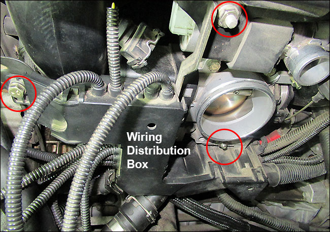
4) Release the three 10mm fastners holding the distribution box (circled in image above).
5) Unplug components (such as oil pressure switch, intake cam position sensor, etc) from the distribution box in order to obtain enough slack to pull distribution box down and away. These connectors are keyed for correct re-installation later.
The throttle plug connector (our objective!) is removed by turning its outer ring counter-clockwise (left) 1/4 turn. This will require forceful initial torque. Use rubberized work gloves for better grip.
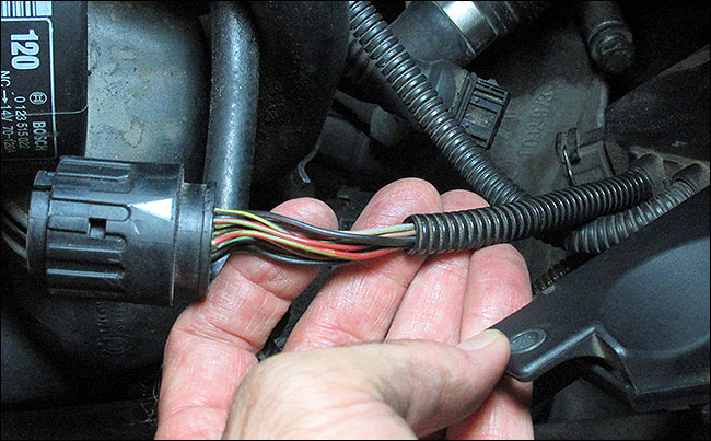
6) Bring forward the throttle connector with attached wire bundle and position it so that its entire length (about 8") is plainly visible and accessible. See image below. Place a heat cloth or similar protective material underneath connector in preparation for wire soldering.
Connector Replacement
Work on one wire at a time. Pin numbers are stamped on both sides of plug connector. Wire color is not important since each new pin wire must be labeled.
1) Starting with pin #1, snip its wire from behind plug and strip a 1/2" end section. Then prepare a new pin wire by trimming it from its 20" length down to 6" and strip a 1/2" end section.
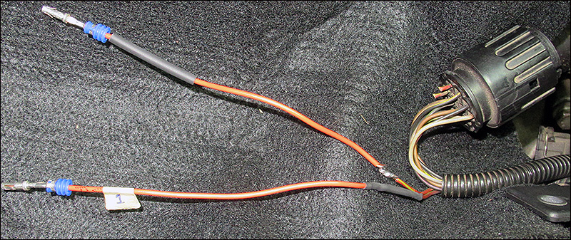
Slip a piece of heat-shrink tubing over the new wire and twist the stripped ends together. Apply solder to secure the splice and ensure a good connection. (An assistant might be helpful here - to hold the wires.) Then apply the heat-shrink tubing over the joint. Finally, attach a small tape label to number the pin wire.
In image above, note how pin wire #1 has been labeled, with heat-shrink tubing covering the splice, while pin wire #2 has just been soldered and is awaiting heat-shrink tubing and a tape label.
2) Repeat Step 1 for all remaining pins.
3) With all pins now re-wired, gather and insert the bundle - a few pins at a time - thru the rubber grommet:
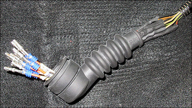
Note how each pin wire is labeled, since matching wires to their corresponding color at this point is not possible. Note further that extra heat wrap has been applied to some solder joints for additional protection.
4) Starting with pin #1, insert pin wires into their corresponding position on the new plug connector. Drive the pins home using a pin tool as discussed in Getting Started. Verify new connector is in "unlocked" position to receive pins.
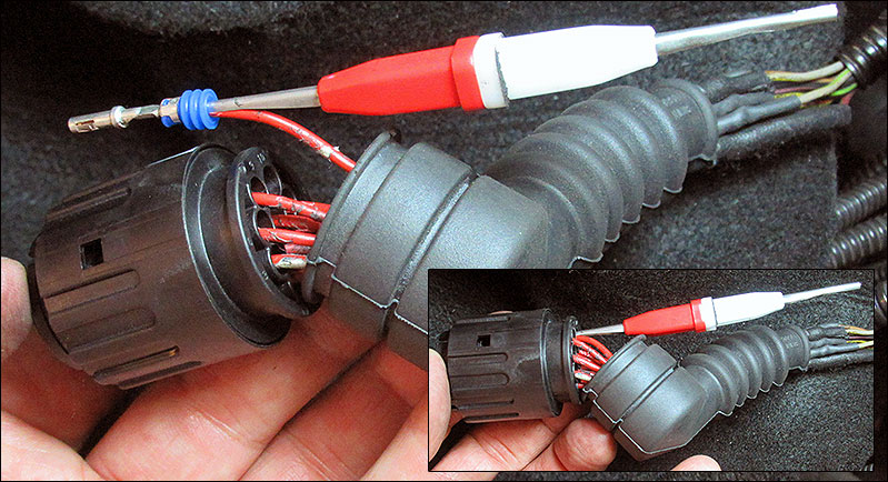
Insert pin tool underneath blue grommet in order to make contact with the metal pin, as shown in image above. This avoids crushing or tearing the blue grommet. Pins should "snap" in place when seated correctly in plug, and extend to the tip of the plastic pin slot on the reverse side of plug. Inset image above shows pins fully inserted.
After inserting each pin, its tape label should be removed to reduce clutter and avoid the tape deteriorating from engine heat.
5) Pull rubber grommet around rear perimeter of new plug connector. Then, wrap exposed length of remaining wire bundle with heat wrap as illustrated below:
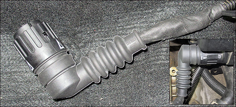
The new plug is ready!
Position new plug connector against throttle body plug with pin 1 at top and pin 10 at bottom. The lower pointer on the plug ring should be aligned with arrow on throttle body. Then twist plug ring clockwise onto throttle body until upper pointer aligns (1/4 turn). Inset image above shows new connector installed.
6) Reinstallation is now reverse of removal.
Address any other issues noted during the course of this procedure such as defective oil return hose, exposed engine wiring or throttle cable sheath, broken plastic parts, etc.
Now, say good riddance to throttle body faults!